
Inquiry
Form loading...

What Is Double Arc Forming and How Does It Work?

Double Arc Forming describes a way to shape material through two coordinated curved forming paths or tool surfaces. The exact setup can vary by industry, so the term should not be treated as one universal machine design. In practice, the process aims to create a controlled profile while managing how the material bends and transitions between curves. The name sounds simple. The setup may not be.

Imagine a metal sheet moving against shaped tooling: contact pressure, tool alignment, and material thickness all influence the final form. A small change in radius can affect springback, surface marks, or dimensional accuracy. Operators may check the part with gauges or a template, then adjust the tooling or forming sequence. These details matter. They are also where a neat diagram can leave out real shop-floor complexity.

This introduction explores what Double Arc Forming means, how the basic operation works, and which factors influence its results. It also distinguishes the process concept from other bending and forming methods that may use similar language. Material choice, machine capability, and part geometry should guide any practical assessment. Not every curved component suits this approach. That point is easy to overlook, and worth reconsidering before comparing methods. When terminology differs between suppliers, ask for drawings, process details, and measurable tolerances rather than relying on the name alone.
What Is Double Arc Forming and How Does It Work?

What Is Double Arc Forming?

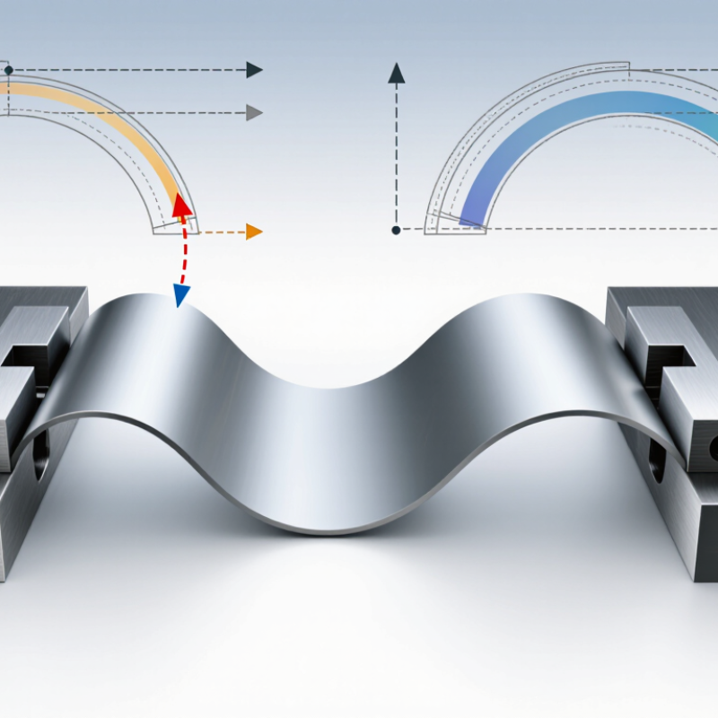
Double arc forming shapes a flat sheet into two connected curves, often across its length and width. The term is not used identically across every workshop, so confirm the intended geometry before specifying tooling. In a common approach, a press or forming rolls gradually bend the blank along two axes. One arc sets the main sweep; the second adds crosswise curvature. The result can fit a curved panel or enclosure more closely than a single-radius bend.

Operators typically check the material grade, thickness, target radii, and grain direction before forming. They may make trial pieces, then adjust the tooling for springback. Watch for wrinkles, local thinning, and visible tool marks. Small changes in pressure can alter the surface. It is not always predictable. The World Steel Association’s World Steel in Figures 2024 reports 1,892.2 million tonnes of crude steel production in 2023. This is industry context, not a measure of forming performance; the report does not specify double arc forming yields. For a reliable result, record trial dimensions and inspect the finished part against the drawing. One detail is easy to overlook: the two radii may interact, so checking each curve separately can miss a poor overall fit.

The Role of the Two Arcs

In double arc forming, two electric arcs deliver heat to a workpiece, often metal, so localized expansion and cooling can shape it. Their roles are related, but not identical in every machine. The exact arrangement depends on the process and equipment.

One arc may provide the main heat, creating a hot zone where the material softens and begins to move. The second arc can heat a neighboring area or balance the temperature pattern. This matters because uneven heating can cause unwanted bending, surface marks, or residual stress. A technician watches the arc position, travel speed, and the changing color of the metal. Small shifts count. Too much heat can thin or distort a section; too little may produce little movement.

Together, the arcs give the operator more control over where heat enters the workpiece. They do not automatically make forming more accurate. The distance between arcs, current, material thickness, and cooling rate all affect the result. A thin sheet may respond quickly, while a thicker plate needs more energy and careful monitoring. The terminology is not perfectly consistent across workshops, so process details should be checked against the specific equipment and material.

That part is easy to overlook.

Equipment and Materials Used

Double arc forming uses shaped tooling to bend sheet or plate into two connected curved sections. A typical line includes a hydraulic or mechanical press, matched arc dies, clamps, and a back gauge. Some setups use a mandrel to support the inner surface and reduce wrinkling. Operators check radius and springback with templates or measuring gauges after each pass. Small details matter.

Common work materials include low-carbon steel and aluminum sheet; the suitable grade and thickness depend on the required radius, finish, and machine capacity. World Steel Association data puts global crude steel production at 1,892 million tonnes in 2023, illustrating steel’s scale as an industrial material—not the performance of any forming method. Before production, technicians should review material certificates and trial-bend a sample. Even then, springback can vary between batches. That is easy to underestimate. Tool alignment, die wear, and uneven clamping can also leave mismatched arcs or surface marks. There is no single universal setup: confirm the die geometry and machine limits for the specific part, and record inspection results.

What Is Double Arc Forming and How Does It Work? - Equipment and Materials Used
Category Equipment or Material Purpose in the Process Practical Details
Process overview Double arc forming Shapes a workpiece to produce two curved sections or a profile with two arcs. The exact tooling and sequence depend on the part geometry. “Double arc forming” does not describe one universal machine setup or set of process parameters.
Forming machine Hydraulic or mechanical press Supplies the force needed to press material into or against forming tooling. Press capacity, stroke, and bed size must be selected for the material, thickness, tool design, and required part dimensions.
Forming machine Roll-forming or bending equipment Applies progressive or controlled bending when the part geometry is suited to a rolling or bending method. Roll arrangement and adjustment affect the resulting curvature. A press may be more appropriate for parts formed with matched dies.
Tooling Matched punch and die, or forming rollers Defines the intended arc profile and supports the workpiece during forming. Tool geometry, clearance, surface finish, and alignment should be matched to the workpiece and the desired dimensions.
Workholding Clamps, stops, and locating fixtures Positions and restrains the workpiece to help maintain repeatable forming and alignment. Correct location is particularly important when the two arcs must remain symmetrical or meet at specified reference points.
Controls and inspection Press controls, gauges, and profile templates Controls the forming cycle and checks dimensions or curvature. Inspection may include arc radius, overall dimensions, symmetry, surface condition, and springback after the load is removed.
Material Low-carbon steel sheet or strip Commonly used where a formable, widely available metal is suitable for the part. Formability depends on grade, thickness, temper, grain direction, and bend radius. Test forming may be needed to confirm the setup.
Material Aluminum sheet or strip Used when low weight and corrosion resistance are important. Forming behavior varies substantially by alloy and temper; some conditions are more prone to cracking during tight-radius forming.
Material Stainless steel sheet or strip Used when corrosion resistance or strength is required. Grade and thickness influence forming force and springback. Tooling and process settings should account for the selected material condition.
Material Copper or copper-alloy sheet Used for applications requiring copper’s conductivity or other material-specific properties. Alloy and temper affect ductility and surface response; suitable forming limits should be verified for the actual stock.
Process aid Forming lubricant, when appropriate Can reduce friction between the workpiece and tooling during forming. Use depends on the material, tool surface, and process. Lubricant compatibility and cleaning requirements should be considered.
Typical sequence Prepare, locate, form, release, and inspect Provides a controlled sequence for producing and checking the curved profile. Springback can change the final shape after unloading, so the finished part should be measured and the tooling or process adjusted if necessary.

How the Double Arc Forming Process Works

In sheet-metal work, double arc forming shapes a blank into two controlled curved regions. The exact arrangement depends on the machine and tooling. A typical setup uses matched curved tools to support and press the sheet. The operator positions the blank, checks its alignment, then applies pressure in stages or along a controlled pass. The metal bends around the tool radii. Small changes matter.

World Steel Association’s World Steel in Figures 2024 reports 1,888.2 million tonnes of crude steel production in 2023. That figure describes the industry’s scale, not the performance of any single forming method. For each part, technicians select tool spacing, bend sequence, and pressure based on sheet thickness, alloy, and target radii. They also account for springback: metal can relax slightly after pressure is removed. A trial piece helps reveal the difference. Too much force may cause wrinkles or surface marks; too little can leave the arcs shallow. Technicians inspect the finished profile with gauges or templates and adjust the setup when measurements drift. This process is repeatable, but not automatic. The first settings may need revision.

What Is Double Arc Forming and How Does It Work?

The chart shows the general order of operations: prepare the workpiece, form the first arc, form the second arc, then inspect the finished profile. Step numbers indicate sequence only—not forming time, force, or machine settings.

Applications and Key Process Considerations

Double arc forming shapes a workpiece into two curved sections, often with different radii or directions. Depending on the tooling, the arcs may meet smoothly or connect through a short transition. The method is useful for curved panels, ducts, machine covers, and architectural components where a single-radius bend will not fit the design. Small differences matter.

In practice, operators set the tool gap and forming pressure, then feed the material through in controlled passes. They check the profile against a template or drawing as it develops. Material thickness, alloy, grain direction, and temper all affect how readily the sheet bends. Springback is a common concern: the metal can relax slightly after pressure is removed. A test piece helps reveal that behavior before a full run.

For consistent results, keep the feed speed steady and inspect both arcs, not just the outer edge. Watch for wrinkles, surface marks, or a sharp kink between curves. These can indicate uneven pressure or a poorly matched tool setup. Tight radii may require more passes, while thin sheet can distort if clamping is excessive. There is no perfect setup for every material; recording adjustments and checking the finished part against tolerances makes repeat production more dependable.